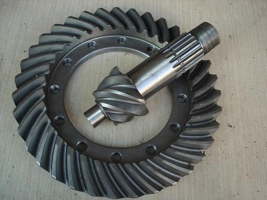
(1) Basin corner tooth product marking and identification
1. In the bevel gear journal end face and the driven bevel gear outer circle to the corner face, the paired serial numbers of the bevel gear and English capital letters are written by the electric pen, and the two serial numbers are the same.
2. The change value of the installation distance of the driving cone gear is engraved on the end face of the driving bevel gear journal. (in mm)
3, product certification. When using the product, be sure to count the number of teeth of the active bevel gear and the driven bevel gear, and use the speed ratio specified in the vehicle specification.
4. Anti-counterfeiting mark and anti-counterfeiting date are engraved on the large surface of the driven bevel gear and the journal surface of the driving bevel gear. Please pay attention to the identification.
(2) Installation of potted angle tooth products
1, should be cleaned before installation, so that the surface is clean, no rust spots. The inner ring of the bearing should be used at the same time. In order to make sure that the front wheel and the rear bearing are assembled with the correct clearance, the actual size of the bearing should be carefully measured to determine the total thickness of the gasket.
2. When assembling, the bearing should be heated to about 80-94C and then gently pressed onto the front bearing neck.
3. Tighten the nut M27X15-6g behind the driving wheel, and tighten the torque between 400-450Nm. At this moment, the torque required to rotate the driving gear is between 1.0-2.5Nm. The spring is used to hook the flange hole and pull it. The pull of the gear is between 16.34-40.87N.
4. After installing the main cone assembly on the reducer housing, install the driven wheel and clean the coupling nut with the differential case, and apply the fastening glue GY340# and LT271# on the thread surface. Adjust the axial position of the driven wheel so that the meshing clearance of the gear pair is between 0.2-0.4mm, and then perform trial operation to ensure that the position of the contact spot is in the middle of the tooth surface, the small face of the positive face, and the reverse face can be large. The end, contact spot width is generally not less than 7mm.
(3) Adjustment of pot tooth
1, when the tooth top contact occurs too heavy (driven gear surface) can reduce the thickness of the gasket between the bearing and the reducer shell, when the contact spots appear in the tooth root, the thickness of the gasket can be increased, and repeatedly adjust the test Until the contact spot is located in the middle of the tooth surface, the tip can be slightly offset, and the minimum distance from the driven gear is 0.8 mm. Absolutely no line contact with the roots is allowed.
2. When adjusting the spots, re-adjust the axial position of the driven gear so that the tooth side is maintained between 0.2-0.4mm. At this time, the nuts with external threads on the left and right ends of the differential assembly should be adjusted so that the rotational force of the assembly can be 1.5-3.5 Nm, and the bolts should be tightened.
Butterfly Valve,Wafer Butterfly Valve,Double Flanged Butterfly Valve
Butterfly Valve,Check Valve,Gate Valve Co., Ltd. , http://www.fw-valve.com