 Transformer capacity calculation - Temporary elimination method when the transformer cannot be stopped: External lead wires, when the fault current is large, can temporarily open the line operation. However, monitoring must be strengthened and the cores appear to have a floating potential after the fault point disappears. Multi-point faults are unstable, and a slip wire resistance can be connected in the working wiring to make the current limit 1A or less. Slip line resistance selection is to divide the normal operating wiring open test voltage by the line current.
 Transformer capacity calculation method:
1. Calculate the capacity according to the load factor βM at which the efficiency of the transformer is highest.
After the calculation load of the building is determined, the total installed capacity of the distribution transformer is: S=Pjs/βb×cosφ2(KVA) (1)
In the formula, Pjs  - the active calculation load KW of the building;
Cosφ2 - the average power factor after compensation, not less than 0.9;
Βb - transformer load factor. 
Therefore, the final determination of the transformer capacity lies in the selected transformer load factor βb. 
The highest efficiency is βb=βM=Po/PKH(2)
In the formula Po, the no-load loss of the transformer;
PKH  - short circuit loss of the transformer. 
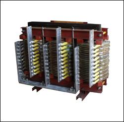
However, in high-rise buildings, equipment rooms are mostly located in the basement. To meet the requirements of fire protection, general information about distribution transformers is available at: Power Transmission and Distribution Equipment
With dry or epoxy cast transformers, Table 1 is the best load rate of domestic SGL power transformers. 
The best load rate of domestic SGL power transformers
Capacity (KVA) 500 630 800 1000 1250 1600
No-load loss (watts) 1850 2100 2400 2800 3350 3950
Load loss (Watts) 4850 5650 7500 9200 11000 13300 Source: http://tede. Cn
Loss ratio α2: 2.62 2.69 3.13 3.20 3.28 3.37
Optimal load rate βm% 61.8 61.0 56.6 55.2 55.2 54.5
MP-35Kv Bus Bar Heat Shrinkable Sleeve
Product Description:
MP-35KV heat shink busbar sleeve, known as copper bar protection tube, Bus bar Insulation Heat Shrinking tube is made of cross-linked environmental protection polyolefin PE heat shrinkable materials which is bombarded by high power electron beam.
Bus bar Energy Heat Shrink Tubing with good resistance to bending and scratching, high insulation strength and resistance to electric carbon mark, applies to switchgear, substation bus, busbar, electrical equipment for anti-corrosion and insulation protection. Bus Bar Heat Shrinkable Sleeve it`s widely used in electric power industries.
Feature & benefit
a) resistance to flame and corrosion.
b) with superior insulated and chemical properties.
c) Shrink ratio: 2/1 (1 kV, 35 kV, 10 kV busbar )
d) environmental friendly, high strength, good elasticity, flame-resistant, soft.
Operating indexes:
a) Min. Shrink temp.: 80 degrees Celsius
b) Final shrink temp.: ~12 degrees Celsius
c) Operating temp.: -55~125 degrees Celsius
Up to standard:Approvals
Meet RoHs compliant
Product images:

Energy Heat Shrink Tubing
Energy Heat Shrink Tubing,Heat Shrink Tubing,Large Energy Heat Shrink Tubing,Heat Shrink Tubing for Busbar,Busbar Heat Shrink Tubing
KEYUACE Materials Co., Ltd. , http://www.insulationtubing.com