Application of ANAPF active filter device in the application of active filter device in 0.4KV small and medium enterprise power distribution system

1 Introduction With the continuous maturity of power electronics technology, non-linear equipment such as energy-saving lamps, computers, and photocopiers are being widely used in residential and office buildings. Harmonic pollution in low-voltage distribution systems is becoming more and more serious. And the user's requirements for power quality are getting higher and higher, harmonic problems have attracted more and more people's attention. Effectively controlling harmonics and keeping them within the allowable range becomes an issue that power workers must consider.
2 Main harmonic pollution sources in low-voltage distribution systems The main source of harmonic pollution in low-voltage distribution systems. When a sine wave voltage is applied to a nonlinear load, the current becomes a non-sinusoidal wave, and the non-sinusoidal current is generated at the impedance of the grid. The voltage drop causes the voltage waveform to also become a non-sinusoidal wave. Fourier series decomposition is performed on non-sinusoidal waves. The component whose frequency is the same as the power frequency is called the fundamental wave, and the component whose frequency is greater than the power frequency is called harmonic. Most of the loads that are widely used today are nonlinear, such as rectifiers, inverters, electric arc furnaces, welding equipment, UPS, elevators, air conditioners, energy-saving lamps (fluorescent lamps), copiers, etc. These non-linear loads generate a large amount of harmonic current. It is injected into the power grid to make the grid voltage distorted. This kind of harmonic pollution will cause serious harm to the power grid and users.
3 Harmonic damage to low-voltage distribution system Harmonics damage to low-voltage distribution system Increase transmission line loss, shorten transmission line life; increase transformer copper consumption and iron consumption, reduce transformer output; cause misoperation of power distribution equipment or Rejection, resulting in power outages; affecting motor efficiency and normal operation, generating vibration and noise, shortening motor life; causing harmonic amplification or resonance problems; causing errors in various measurement instruments of power systems; interfering with communication systems, damaging sensitive equipment; A large current on the neutral line causes a system failure.
4 Harmonic control measures for low-voltage distribution network Harmonic treatment measures for low-voltage distribution network There are two main harmonic control measures for low-voltage distribution network: First, active measures, that is, starting from the harmonic source itself, so that it does not generate Harmonic or reduce the content of harmonics of its output; second, passive measures, that is, by installing a power filter, filtering harmonics generated by harmonic sources, or impeding the harmonics of the power system from flowing into the user's power grid. Active measures include multi-pulse rectification, pulse width modulation (PWM), matrix converters, four-quadrant converters, and more. Active measures can effectively limit the generation of harmonics, but due to the diversity of nonlinear loads, it is impossible to completely eliminate harmonic currents by active measures. Passive measures mainly include PPF and APF.PPF which has emerged in recent years has been widely used for its low cost, simple structure and convenient maintenance, but its shortcomings are difficult to overcome, such as filtering only harmonics of specific frequencies. It is easy to parallel resonance with the system, and the filtering effect on the undulating load is not ideal. APF has the characteristics of fast response, strong filtering capability, flexible installation and convenient expansion. It has been widely used in recent years.
5 APF (Active Power Filter) Principles and Features (Active Power Filter) Principles and Features The ANAPF series of active power filter devices are connected in parallel to the grid to detect harmonics and no load in real time. The power component uses PWM converter technology to generate a reverse component corresponding to the current harmonic component and the reactive component from the converter and inject it into the power system in real time, thereby realizing harmonic control and reactive power compensation.
The principle is as follows:
ANAPF not only has the function of filtering harmonics, but also provides leading or lagging reactive current for improving the power factor of the grid and realizing dynamic reactive power compensation. At the same time, it also compensates for the three-phase unbalance function and reduces the current flowing through the neutral line. ANAPF uses the instantaneous reactive power theory to extract harmonic components and respond to load changes within 20μs. The full response time is 20ms, which can be used in applications where the load fluctuates rapidly. ANAPF can compensate for 2 to 50th harmonics. ANAPF has an automatic current limit function that does not overload. ANAPF protection measures are complete to ensure the safe operation of equipment. The ANAPF customization is powerful and can be set to compensate only harmonics, only compensate for reactive power, or both. ANAPF uses a large-capacity, high-definition human-machine interface color touch screen, which can display various voltages, currents, harmonics, power factor and other electrical parameters in real time. The menu is displayed in Chinese, with pictures and texts, and can display real-time device operating parameters and historical event records. The display interface can touch settings, and the operation is simple and quick. The ANAPF design is simple to select and does not require detailed grid analysis. It only needs to measure the harmonic current. ANAPF is easy to install and easy to expand. It can flexibly choose different installation modes according to the actual situation of the load and distribution system, as well as the expected compensation effect, so that the investment is less effective. According to the ANAPF installation location, it is divided into two types: comprehensive compensation and local compensation. ANAPF has two series of three-phase three-wire and three-phase four-wire, with capacity of 50A, 100A, and 150A, which can meet the needs of different users.
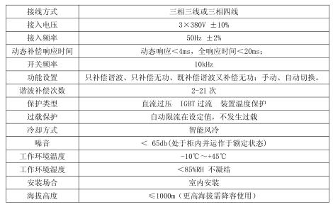
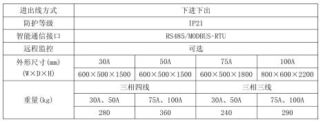
6 APF (Active Power Filter) main technical indicators (active power filter) main technical indicators

8 ANAPF specific application in low-voltage power distribution system in a low-voltage power distribution system. A small and medium-sized enterprise in Shanghai, the transformer capacity is 150kVA. When a large number of air conditioners are turned on at the same time in winter, the circuit breaker will trip, seriously affecting The daily operation of the company. After investigation, the company has a large number of non-linear loads such as energy-saving lamps, inverter air conditioners, computers, printers and elevators. It is these non-linear loads that reduce the output of the transformer. Studies have shown that harmonic currents can cause the outer silicon steel sheet or some fasteners of the transformer casing to heat up, which may cause local overheating, accelerate the aging of the dielectric medium, cause insulation damage, and reduce the service life of the transformer. The presence of harmonics increases the apparent power. Regardless of the harmonics, the relationship between the apparent power S and the active power P and the reactive power Q is; in the case of harmonics, the harmonic power D must be considered. , the relationship is; and D and Q, can not be converted into useful power. It can be seen that harmonics have a significant negative impact on the efficiency of the transformer. According to the actual survey and analysis, the company's transformer margin is not large, but if the harmonics are reduced to meet the requirements of the national standards, it can meet the daily power supply requirements, there is no need to expand. According to the investigation and analysis of the company's electricity load, it is found that the lighting circuit load is large, and because the lighting circuit uses a large number of energy-saving lamps, the harmonic content of the circuit is relatively high, which is the main reason for reducing the output of the transformer. The illumination circuit is measured with FLUKE 434 to obtain the current waveform as shown in Figure 1. As can be seen from the figure, the current waveform is far from the ideal sine wave, and the distortion is more serious. Distortion of the current waveform can cause distortion of the voltage waveform and thus affect the normal operation of other devices such as a computer. At the same time, the N-phase current reaches 37A, and the current imbalance problem is also prominent, and there is a large power hazard. The fractional harmonic content data is shown in Figure 2. It can be seen from the figure that the THDi of phase A, phase B, and phase C are 19.7%, 27.8%, and 26.6%, respectively, and the harmonic pollution is very serious, posing a safety hazard.
According to the harmonic content, the ANAPF with rated capacity of 50A is used to separately compensate the lighting circuit. The current waveform and fractional harmonic content data obtained after the treatment are shown in Figure 3 and Figure 4, respectively.
It can be seen from Fig. 3 and Fig. 4 that the current waveform after treatment is close to a perfect sine wave, and the distortion of the current becomes effective control; the neutral current is also reduced from 37A to 5A, eliminating the excessive current due to the neutral line. The fire hazard caused by the current; the harmonic content of the current has also dropped from about 20% to about 3%, and the harmonic content has been greatly reduced, which has met the requirements of GB T14549-1993 "Power Quality Harmonics of Public Grid". ANAPF effectively reduces THDi, suppresses three-phase unbalance, reduces the current flowing through the neutral line, effectively improves various energy indicators, enables various electrical equipment to operate normally and stably, and prolongs the use of equipment. Lifetime reduces losses due to circuit failure. Through this data collection and analysis, a large amount of reference data has been accumulated, which lays a solid foundation for harmonic control in the future.


EN124 B125 C250 D400  BMC/Smc Manhole Cover and frame


Product description :

16 years experience on Manhole Cover manufacturing and exporting.

International R&D team for your wanted design.

SMC,BMC,ductile iron,grey iron material is available.

Model: B125, C250, D400, E600, F900.

Certiifcate: EN124, BVQI and AS3996.

Size: 200~1200mm in square, rectangle or triangle etc.


Bearing Class / Loading Capacity of Cast Iron Manhole Covers
 
Class Apply to Bearing Remarks
EN124-A15 Areas where only passed by Pedestrians and Bicycles. 15KN  
EN124-B125 Footways, parking lot or similar areas. 125KN HOT-SELLING
EN124-C250 The edge combinative area of vehicle road and the pavement. 250KN  
EN124-D400 Vehicle area and urban arterial road.  400KN HOT-SELLING
EN124-E600 Shipping port and parking apron area.  600KN  
EN124-F900 Airplane taxiway and huge dock. 900KN  

Products show 

EN124 SMC manhole cover


manhole cover

application

manhole cover

factory

equipment

equipment

Composite/SMC Manhole Cover

Composite Manhole Cover,Smc Manhole Cover,Composite Smc Manhole Cover,Plastic Composite Manhole Cover

Hebei Mingda International Trading Co.,Ltd , http://www.mingdacasting.com