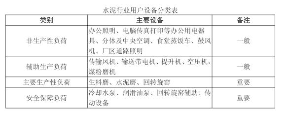
Third, third, industry users participate in the peak-to-peak power-limiting technology program industry users participate in the peak-peak power-limiting technology program (1) Gap level IV-level participation program 1. Staged peak: when the peak-shifting instruction is implemented, priority is given to the participation of some cement mills. Wrong peak. Under the premise of completing the peak-to-peak indicator, combined with its own production process, it can selectively release part of the equipment load at different time periods.
2. After receiving the wrong peak command, the emergency peak should be quickly put into the limit load, and the air-conditioning lighting equipment should be arranged preferentially. If the cement mill is not able to meet the requirements, the cement mill will participate in the peak, and then gradually release the load according to the instructions to resume normal production.
(II) Gap level III participation scheme 1. Staged peak: Under the premise of ensuring safety, all cement mills and some raw mills participate in the peak during the peak period on the basis of the implementation of the IV scheme. . Under the premise of completing the peak-to-peak indicator, combined with its own production process, it can selectively release part of the equipment load at different time periods.
(3) Gap Level II Participation Plan 1. Staged peak: 1) On the premise of ensuring safety, based on the implementation of the Level III plan, all cement mills, raw mills and mines during the peak period The long-distance conveyor belt transmission system participates in the peak. Under the premise of completing the peak-to-peak indicator, combined with its own production process, it can selectively release part of the equipment load at different time periods.
2) For the long-distance transmission belt transmission system equipment with slow response time, it is necessary to participate in the peak preparation in advance to ensure that all load-limited loads can participate in the peak at full time.
2. Emergency peak 1) After receiving the peak error command, it is necessary to quickly input the limit load, and then gradually release the load according to the instruction to resume normal production. 2) On the basis of the implementation of the III-level plan, after receiving the wrong peak command, quickly put all the cement mills and raw material mills into operation, and if necessary, stop the main power equipment of the rotary rotary kiln, and enable the auxiliary transmission equipment to achieve the load-limiting purpose. Then gradually release the load according to the instructions to resume normal production.
(4) Gap Level I Participation Plan 1. Staged peak: 1) Considering the large power gap, the company can be arranged for maintenance throughout the plant, leaving only the power load required to repair the equipment. 2) In the peak period, firstly input the load-limited equipment such as the cement mill, the raw material mill and the main power equipment of the rotary rotary kiln with high limit load and fast response time; and gradually input the long-distance transmission of the mine with slow response time. With a conveyor system, all load-limited loads are guaranteed to participate in the peak.
2. Emergency peaks need to be quickly put into the limit load of the cement mill, raw mill and main power equipment of rotary rotary kiln after receiving the peak-level command, and then gradually release according to the instructions. The load resumes normal production.
Fourth, fourth, industry users participate in the peak power limit risks and precautions Industry users participate in the peak power limit risks and precautions 1. Stop the clinker and raw material grinding system risks and precautions must be prepared in advance, until all materials are exhausted After that, it can stop the machine. Otherwise, the hoist will not be able to start under heavy load, or the conveyor will be blocked by the powder, which will cause the system to transfer the powder normally after a long time. The preparation time usually takes 10 minutes.
2. The long-distance conveyor belt transmission system of the mine must be prepared in advance. After all the mineral materials on the conveyor belt have been exhausted, it can be shut down. Otherwise, the conveyor belt will not be able to be turned on again under heavy load. The preparation time is determined by the transmission distance, generally not less than 30 minutes. 3. The rotary rotary kiln cannot be stopped urgently, and the rotary kiln auxiliary transmission should be activated within 10 minutes after the main power equipment is stopped. Otherwise, because the length of the rotary rotary kiln reaches tens of meters, in the case of emergency stop, the kiln body will be deformed, the internal refractory bricks will loosen, and the clinker will harden and block the kiln body. It takes a long time (72 hours) to empty the material when it is full.
Therefore, the industry should not use forced power or remote control equipment to control power cuts. Enterprises should formulate effective internal emergency plans, actively cooperate with peak implementation, prevent malicious accidents, and take the initiative to take social responsibility and minimize losses.
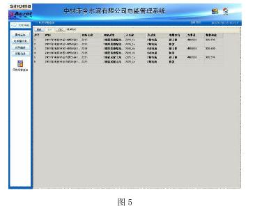
V. Function and application of intelligent power monitoring V. Function and application of intelligent power monitoring Zhongping Pingxiang Cement Co., Ltd. is a large electricity consumer in Pingxiang City, Jiangxi Province. The annual production cost of the old production line is tens of millions of RMB, so users pay great attention to the team. Electricity assessment. The power management system designed by Ankerui for its old production line performed well, and the power management system of the new 4500t/d production line was still designed by Ankerui. 5.1 Project Overview
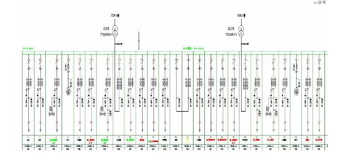
The user will record the production electricity consumption every two hours, and perform the assessment according to three shifts in the morning, midnight and evening. The morning shift time is 8:00am~4:00pm, the middle shift is 4:00pm~12:00pm, and the night shift is 0:00am. ~8:00am. Compare the data of the total transformer substation with the data of the distribution room of the production line once a week, compare it with the power consumption data provided by the power supply bureau every month, and use this as the basis for assessing the energy consumption of each group. 5.3 System Structure The entire system is designed with a set of Acrel-3000 power management system, which adopts a layered and distributed structure, namely the field equipment layer, network management layer and monitoring management layer, as shown in Figure 1:
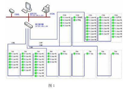
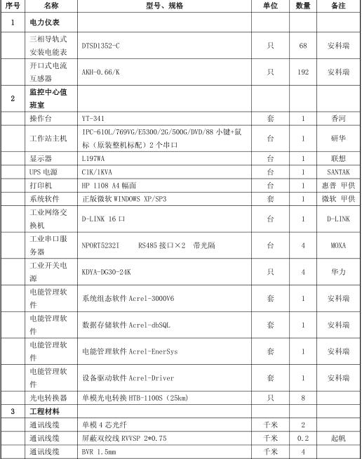
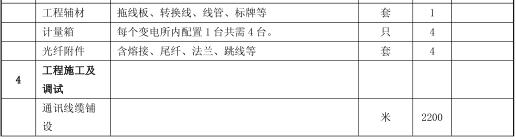
Because the advanced system is small, the communication management equipment selects the 4-port serial port Jetport5604I produced by Korenix, which can simultaneously integrate 4 RS485 buses with optical isolation. The serial port server is installed in the network cabinet of the central control room, and is connected to the station management layer through the industrial Ethernet TCP/IP protocol. The Ethernet transmission medium is a super five types of STP shielded lines. Industrial network switches are reserved in this project for future system expansion. The main equipment of the station management layer is DELL's workstation, Santak 1KVA tower UPS power supply and HP's A4 format printer, operating system software Windows XP SP3, and power management system software for the Acrel-3000 series. All the equipments in this project use wired connection. The communication network construction is completed before the start of the new line production line. The system commissioning is completed during the trial operation. The power management system was put into operation at the same time in December 2011 with the production line.
5.4 System function data acquisition and management Data collection and management The data acquisition required for power distribution mainly through the ACR320E network multi-function instrument, PT, CT and other devices, will be the operating parameters of the field electrical equipment, including: current, voltage, active power, The remote sensing information such as reactive power, power factor, active power, and the state of the circuit breaker opening and closing are collected. The instrument is connected to the intelligent communication server through the 485 bus, and is connected to the power management host through the Ethernet interface. The ACR320E network multi-function meter adopts the RS485 interface and the MODBUS-RTU communication protocol, and the RS485 adopts the shielded cable twisted pair transmission, and the wiring is simple and convenient; The communication interface is half-duplex communication, and the maximum data transmission rate is 10Mbps. The RS-485 interface is a combination of balanced driver and differential receiver. The anti-noise capability is enhanced. Up to 32 devices can be connected on the bus. The maximum transmission distance is 1.2km.
Information processing information processing Statistics, analysis, and calculation of real-time data collected by the signal acquisition system, and the data is periodically stored. For the same period of electricity units, different power units in the same period of electricity consumption statistics; as a management platform for electricity costs, compared with the actual electricity costs; according to the amount of power generated by mobile oil, the fuel consumption is estimated. Clearly reflect the electricity consumption of all departments of the whole plant, establish a benchmarking department, and compare with the benchmarking department, find the steps of stealing electricity, leakage, long-lighting, and unused equipment power-off; evaluation of energy-saving effects of different energy-saving schemes It is beneficial to select energy-saving measures in a targeted manner, and can also be used as a measurement system for contract energy management projects; the energy report realizes the time-based inquiry of all energy data, which is divided into five types: minute, hour, day and month;
Power summary table, all monitoring equipment power summary, according to the time period query, automatically calculate the power consumption at any time; print and export, all reports and interfaces can be printed, or exported in EXCEL, WORD format; power report shown in Figure 2.


((4 4) energy-saving product optional rail table or) energy-saving product optional rail table or APFAPF active filter device active filter device lighting box DDSF1352 main function of the meter: current specification 1.5 (6) A, 5 (20) A, 10(40)A, 20(80)A Optional, multi-rate energy statistics, energy pulse output, RS485 communication interface, Modbus protocol or DL/T 645 protocol optional. Dimensions: 76 × 89 × 74mm, 4 modules. Current and voltage measurement for lighting boxes; single-phase energy metering. ARDDTSF1352 main function of rail type electric meter: current specification 1.5 (6) A, 5 (20) A, 10 (40) A, 20 (80) A optional, multi-rate energy statistics, energy pulse output, RS485 communication interface, Modbus The protocol or DL/T 645 protocol is optional. Dimensions: 126 × 89 × 74mm, 7 modulus. Three-phase energy metering for lighting boxes.
Main functions of DTSD1352 rail type electric meter: LCD display, full electric parameter measurement (U, I, P, Q, PF, F, S); four quadrant energy metering, multi-rate energy statistics, maximum demand statistics; current specification 1.5 ( 6) A, 5 (20) A, 10 (40) A, 20 (80) A optional, RS485 communication interface, Modbus protocol or DL/T 645 protocol optional. Dimensions: 126 × 89 × 74mm, 7 modulus. Suitable for power cabinets. The ANAPF series of active power filter devices are connected to the grid in parallel. By detecting the harmonic and reactive components of the load in real time, PWM converter technology is used to generate a corresponding harmonic component and reactive component from the converter. The inverse component is injected into the power system in real time to achieve harmonic control and reactive power compensation.
Seven, equipment list

Magnesium die casting is to melt the magnesium castings and fill the castings under high pressure and high speed, and crystallizes and solidifies into castings under high pressure. The finished products have low density, high strength, and large capacity to withstand impact loads. Can be used as automotive, aerospace and other high-end and new machinery parts aluminum alloy die-casting Aluminum Alloy Die Casting is to melt the aluminum castings in a high-pressure high-speed filling mold, and crystallized in a high-pressure solidification into castings, finished product performance, high precision, toughness High, can be used as precision mechanical parts
Our company is committed to developing the key technology and development trend of new metal manufacturing: the more lightweight SSC / Mg alloy casting; as a professional light alloy Die Casting supplier, we pay more attention to technology accumulation and research development, and put forward the industry innovation trend "magnesium literature", and registered trademarks in China and Germany. Magnesium Zun MEIZUN ", in the automotive industry and the electronics industry, followed by the manufacturing of industrial machinery parts accessories made no small research and development results; the company has about 100 people's design and development team to turn your ideas into products, 101 magnesium alloy semi-solid rheological die-casting, all imported magnesium alloy semi solid die casting machine, supply The largest and most advanced metal forming service


NOTE: All products are photographed in factories
just use as technology sample
Magnesium Die Casting,Die Casting,Injection Molding,Metal Plastic Processing
Ruizhun Precision Metal Co., Ltd. , http://www.rzjmdiecasting.com