I. INTRODUCTION From the perspective of the history of process measurement and control, each major change is often closely related to the change in signal transmission methods. Early pneumatic signals evolved to analog signals of 4 to 20 mA, resulting in electrical meters and instrumentation. After this, with the development of computers, communications, and other technologies, in the mid-1970s, a distributed control system (DCS) emerged, and the computer technology was truly applied to the field of process control, achieving a major leap in automation technology.
In the early 1980s, an intelligent instrument based on the HART protocol was introduced. The HART protocol adopts FSK frequency shift keying technology. Its digital signal is modulated to a 4~20mA analog signal, which realizes digital communication and does not interfere with the transmission of analog signals. Due to its unique Device Description Language (DDL) and other technical features, HART smart meters have been widely accepted and applied.
After the emergence of smart meters, people have great interest in the application of digital communication technology in the field of automatic control. This is because smart meters have increased equipment database, self-diagnosis, fault prediction and other functions compared to traditional meters, making the appearance of the instrument a new look. However, it is an extremely complicated process to form a standard for digital communications that can be targeted at process control, is technically advanced, and can be widely accepted by major instruments and control manufacturers and users. Until June 1994, the two major international organizations ISP (InteroperableSystemProtocol) and North American WorldFIP (WorldFactoryInstrumentationProtocol) organizations formally merged to produce the Fieldbus Foundation.
The Fieldbus Foundation is a non-profit neutral organization composed of more than 100 major control and inspection instrument manufacturers and end users in the world. Its purpose is to develop fieldbuses that are adaptable to process control, openness, interoperability, and standards. It also complies with the IEC (International Electrotechnical Commission) standards under development and the SP50 standard of the ISA (American Institute of Instrumentation and Instrumentation), and is widely represented internationally.
The FF fieldbus is an all-digital, serial, and two-way communication protocol for interconnecting field devices such as transmitters, control valves, and controllers. Fieldbus is a local area network (LAN) existing between process control instruments to achieve decentralized process control within the network.
The most fundamental feature of FF fieldbus is that it is developed specifically for industrial process automation. It has perfect measures to meet demanding use environments, intrinsic safety, hazardous situations, variable processes, and bus power supply. Due to the adoption of standard function blocks and DDL device description technology, it is ensured that the products of different manufacturers have good interoperability and interchangeability. In summary, during the complete life cycle of the automation product from design, installation, operation to maintenance, the FF field bus can bring users various benefits.
Second, FF field bus model and technology overview FF field bus in line with ISO (International Standards Organization) defined OSI (Open Systems Interconnection) model. As shown in Figure 1, it mainly includes three parts: Physical Layer, Communication Stack, and User Layer.
The physical layer corresponds to the first layer of the OSI. It accepts messages from the communication stack and converts them into physical signals transmitted on the fieldbus communication medium, and vice versa.
The communication stack corresponds to the second and seventh layers of the OSI. The seventh layer, application layer (AL), encodes and decodes user-level commands. The second layer, the Data Link Layer (DLL), controls the transmission of information through the first layer. The DDL also manages access to the fieldbus through a defined centralized bus scheduler, the so-called LinkActiveScheduler (LAS). The LAS is used to schedule the transfer of information and the exchange of data between control devices. The FF fieldbus does not use the third, fifth and sixth floor of the OSI. The user application layer is not defined by the OSI model but is defined by the FF itself.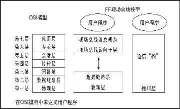 The structure of the FF fieldbus (see Figure 2) provides stable synchronous control and supports asynchronous communication of data, which is used for diagnosis, report generation, maintenance, and troubleshooting. Maintenance tasks can be performed online without disturbing synchronous communication.
The FF data link capability provides an enhanced method of access to control and services for all modern data models. Including Client/Server, Figure 2 Fieldbus Structure Publisher/Subscriber, and Report Distributor. By extending addressing and bridging of secure data transmission, it supports multiple segments at the same time. In addition, it provides more accurate time allocation and synchronization of multi-segment systems, on-line device monitoring and configuration, and online scheduling modification and creation.
1. Physical layer The physical layer is defined according to the standards approved by IEC and ISA and conforms to the physical layer standards of ISAP50.02-1992, IEC1158-2 (1993) and the FF-81631.25kb/s physical layer behavior specification.
The FF field bus uses Manchester-Biphase-L technology coding.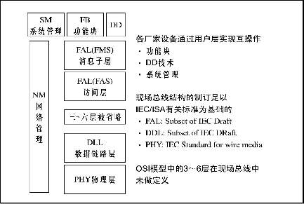
The FF field bus includes H1 and H2 (see Figure 3). The technical specifications of H1 have been completely determined. H2 uses 100Mb/s high-speed Ethernet technology and is expected to release its technical specifications in 1999.
The H1 communication rate is 31.25kb/s, which is suitable for temperature, flow and level measurement applications. Its equipment is directly powered by the bus and can also operate on the original 4-20mA equipment line. H1 can support intrinsic safety (IS) with bus-powered mode. Therefore, an intrinsic safety barrier should be added between the power supply in the safe area and the intrinsically safe equipment in the hazardous area.
The signal waveform of H1 is shown in Fig. 4. The transmitting device transmits a current signal of +10 mA to a 50 Ω equivalent load at a rate of 31.25 kb/s to generate a peak-to-peak voltage of 1 V modulated on the DC power supply voltage (PP ) Voltage signal. The DC voltage range is 9~32V, but in the intrinsically safe application, the allowable voltage range is determined by the safety barrier rating.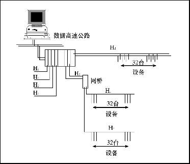
The technical specifications of H2 have not been completely determined yet.
2. Communication stack With reference to Figure 2, the following is a brief overview of the work of each layer of the communication stack.
a. Data Link Layer (DLL)
The DLL is located on the second floor and mainly controls the transmission of messages on the fieldbus. It manages access to the bus through the LAS. The DLL is a subset of the existing IEC/ISA DLL.
The DLL defines three types of equipment, namely, basic equipment that cannot become LAS, master equipment that can become LAS, and bridges that can combine field buses into larger networks.
LAS handles real-time process data separately from back-end MMIs (man-machine interface) and downloads. On the bus, only one active LAS is responsible for managing the bus. It has a list of all the devices on the bus. After the device has been approved by the LAS, it can send a transmission packet to the bus.
Communication over the bus is divided into two categories: Scheduled/Cyclic and Unscheduled/Acyclic communications.
For scheduled communications, the LAS has a transmission schedule that works for all data buffers in all devices that need to be periodically transmitted. When the data transmission time of the device buffer arrives, the LAS sends a forced data (CompelData, CD) to the device. Once the CD is received, the device broadcasts or "publishes" data to all devices on the fieldbus. All devices that are configured to receive data are called Subscribers.
Scheduling communication is often used between fieldbus devices to carry out regular, periodic transmission of control loop data.
Unscheduled communication allows all devices on the field bus to have the opportunity to send non-scheduled messages between dispatch packets. The LAS issues a PassToken (PT) to a device. When the device receives the PT, it allows the use of the fieldbus and sends the message. Unscheduled communication is usually used to transmit information such as alarm events, maintenance/diagnostic information, display information, trends, and configuration.
b. Fieldbus Access Sublayer (FAS)
FAS utilizes the scheduling and non-scheduling features of the DLL to provide services for the message sub-layer (FMS). Its service types include three types:
(1) Client/server type: Used for queuing, non-scheduling, user initialization, one-to-one communication between devices. It is often used for operator-generated requests, such as fixed-value changes, alarm confirmations, and device uploads and downloads.
(2) Report Distribution: Used for queueing, non-scheduling, user initialization, and one-to-many communication. Generally used for fieldbus devices to send alarm notifications to the operator console.
(3) Release/Receive Type: Used for buffering (that is, the latest version of the data is retained in the network), one-to-many communication. It is often used for periodic, user function block inputs and outputs such as process variables (PV) and raw outputs (OUT).
c. Fieldbus message sublayer (FMS)
FMS communication services provide a standard method for user applications. With it, each function block can communicate through this bus. It describes the communication service, the message format and the protocol behavior necessary for the user to establish a message. For different object types, the corresponding FMS communication service is defined.
3. The user application module FF module is divided into the following 3 categories.
a. Resource Block
Describe the characteristics of the device, such as name, manufacturer, serial number, etc. Each device has only one resource block.
b. Function Block
It controls the system behavior and its inputs and outputs can be connected via fieldbus. The execution of each function block is precisely scheduled. There can be more than one function block in one user application. FF defines a standard set of function blocks, such as AI, AO, PID, and so on.
In the field device, by setting up function blocks, the expected functions can be realized. For example, a pressure transmitter can include an AI, and a control valve can include a PID and an AO block. In this way, a complete control loop can be formed by the transmitter and the control valve.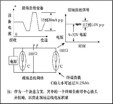 c. Transducer Block
It separates the function blocks from the read sensor and command output to the hardware's local input/output functions. They also contain information such as date and sensor type.
4. System Management
In order for the control system to work properly, the function blocks must be executed at precise time intervals and in the correct order.
System management synchronizes the execution of function blocks on the field bus with the communication of function block parameters; it also handles other important system features such as date and time release for all devices, automatic assignment of device addresses, and parameter names or tag numbers (Tag) search and so on.
5. Device Description
In order to ensure interoperability of FF devices, device description techniques are used in addition to guaranteeing the definition of function block parameters and behaviors. DD is similar to the driver used in the PC to contact the operating printer. As long as there is a device DD, any field bus compatible control system or host can operate the device.
FF provides DD for all standard function blocks and converter blocks. Vendors usually develop “long†DDs based on standard DDs to add vendor-specific features such as calibration and diagnostic procedures to the equipment.
6. System Configuration
It is divided into the following two phases.
a. System Design It is similar to the current Distributed Control System (DCS) design, but there are some differences.
The first is the physical wiring, which changes from a 4-20mA analog point-to-point connection to a digital bus line that connects multiple devices to one cable. Each FF device must have a unique physical device tag and a corresponding network address.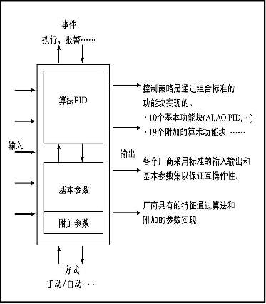
Second, the FF system can distribute some of the control and input/output subsystem functions to fieldbus devices, thereby reducing the number of controllers and remote I/O required.
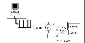
b. After the system configuration system design and instrument selection, according to the control strategy, connect the input and output of the functional block of the device, then the configuration can be realized, as shown in Figure 7. If a device is a link master, a separate control loop can be configured, which allows the loop to run continuously without a configuration device or a central console.
Third, FF fieldbus topological structure and common parts features 1. FF field bus topology FF field bus topology is more flexible, as shown in Figure 8, usually includes point to point type, with branch bus type, daisy chain type ( DaisyChain) and tree type. At the same time, these structures can also be combined to form a hybrid structure. Among them, bus-type and tree-type with branch are used more in the project.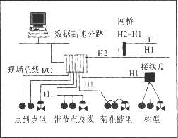
a.Buswith Spur with Branch
In this configuration, the fieldbus device is connected to the bus segment through a cable called a branch line. The length of the branch line is from 1m to 120m, and the branch line less than 1m in length is regarded as a splice. It is suitable for applications where the physical distribution of equipment is relatively decentralized, equipment density is low, and new installations are used. Equipment disassembly on the branch has no effect on other equipment.
b. Tree
Devices on a fieldbus segment are connected to a common junction box, terminal, dashboard, or I/O card in a separate twisted pair. It is suitable for applications where fieldbus is locally concentrated, high density, and upgrades of existing equipment to fieldbus. With this topology, the longest length of the spur must be taken into account.
2. Common Component Characteristics a. Cables Various types of cables are available for fieldbus.
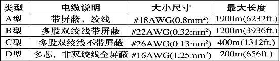
Table 1 lists the cable types specified in the IEC/ISA physical layer standard. The Type A cable is the preferred cable that meets the IEC/ISA physical layer conformance test. Alternative type A cables are Type B cables, which are commonly used in new plant and retrofit projects where multiple fieldbuses operate in the same area. Type C and D cables are generally not recommended.
b. Terminator It is an impedance matching module installed at or near each end of the transmission line. Each field bus segment needs two. Its role is to prevent signal distortion and attenuation.
c. Power According to the FF physical layer profile specification, the power supply will be designed into the following three types:
(1) Type 131. The non-intrinsically safe power supply is designed for the power supply of the explosion-proof grid, and its output voltage depends on the explosion-proof grid power (rating).
(2) Type 132. Non-intrinsically safe power supply, not used for intrinsically safe explosion proof grids. The maximum output voltage is 32VDC.
(3) Type 133. Intrinsically safe power supply, in accordance with recommended intrinsically safe parameters.
In order to ensure the normal operation of the fieldbus, the impedance of the power supply must match the network. Whether it is a built-in or external fieldbus power supply, this network is a resistor/inductor network.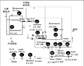
IV. Field test of FF in Monsato, USA In November 1995, FF conducted an on-site Beta test at the Monsato Chocolate Bayou plant. The manufacturers participating in the trial included Fisher-Rosemount, Honeywell, Foxboro, Micro-Motion, Yokogawa, Smar, E+H, etc. The host of the trial was Fisher-Rosemount's PROVOX system. The main contents of the experiment include communication scheduling, alarms and online function blocks.
As shown in Figure 9, it is a boiler coolant recovery system in which the appropriate fieldbus measurement and control equipment is installed.
As shown in Fig. 10, the fieldbus area is divided into two parts, areas 1 and 2. Through the H1 bus, related functional blocks are linked into specific measurement and control loops.
As shown in Figure 11, here, the host only assumes the tasks of configuration and monitoring, and the basic measurement and control functions are performed by on-site equipment.
This field test verifies key technologies and demonstrates the interoperability of different manufacturers' products in the same system. Of course, it is only a test system that was dismantled shortly after the test was completed.
After this, at the ISA exhibition in the United States in October 1996, FF showed fieldbus technology that has been completed and obtained control tactics for recognizing 11 fieldbus applications, more than 70 FF devices and 8 control systems from 37 manufacturers. Operate through 13 fieldbus connections.
V. Fisher-Rosemont Integrated Fieldbus Solution Since the introduction of the FF Fieldbus, PlantWeb plant management network structure has brought a profound change to the process management, it combines intelligent field devices, standards and scale Variable platform technology and integrated modular software provide a more efficient and user-friendly approach to improving process performance. On the basis of lower overall price than traditional DCS-centric solutions, PlantWeb provides more features.
Fisher-Rosemont further introduced the integrated fieldbus solution, PlantWeb-Builder, as shown in Figure 12. It mainly includes:
(1) FF measurement and analysis instruments. Such as 3051 pressure transmitter, 3244MV temperature transmitter, 5300 mass flowmeter 8800A vortex flowmeter, 4081pH meter and so on.
(2) FF valve and actuator with digital controller. Such as DVC5000F valve controller and ELQ series valve actuators.
(3) DeltaV with integrated management capabilities (built-in AMS equipment management software) and scalable control system.
(4) Other required equipment such as power supply, protective equipment and junction box.
(5) Technical support for project implementation.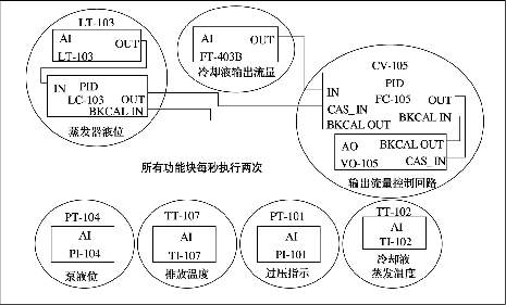
PlantWebBuilder not only fulfilled the technical promise of FF fieldbus, but also added some new features, mainly reflected in:
a. Realize the control in any place Adopt FF technology, the on-the-spot equipment can carry out the control algorithm without relying on the control system, make PID control can be loaded into the on-the-spot equipment.
PlantWebBuilder's unique, anywhere control provides more functionality because in this solution, the common functional blocks used in field devices are exactly the same as in the DeltaV control system. Device-based control has the advantages of improved control response, reduced dead time, and the like; it also reduces the load on the control system so that the control system can perform advanced functions such as batch processing and inspection control.
b. Built-in AMS equipment management software In this program, it is worth AMS management software to enable users to easily check the wiring and configuration equipment in front of a PC or workstation. In practical applications, the user can save the installation cost. More than 30%. At the same time, it is possible to use the diagnostic function of AMS software to check the equipment and issue an alarm signal before the problem is serious, or confirm the fault in the control room before the technician goes on-site inspection, thereby reducing the equipment downtime; and making the site changeable. The working conditions of the feeder and the valve are always kept optimal, improving the consistency and availability of the process.
c. Less Risk and More Flexibility with Integrated Solutions Considering the difficulties users may encounter when initially applying FF fieldbus technology, the integrated solution allows users to use FF fieldbus technology faster. The program's German fieldbus products have been tested not only in the laboratory but also in the field.
It should be emphasized that although PlantWebBuilder's FF integration solution is complete, it is also open, that is, all products that have obtained the FF interoperability test tag, as well as application software that conforms to the OPC standard can be integrated into the solution. And, through the OPC, Modbus, 4 ~ 20mA, HART and discrete I / O can also integrate the user's existing equipment and systems.
VI. APPLICATION EXAMPLES 1. World's first FF fieldbus system for commercial operation On April 15, 1997, at the large-scale chemical plant in Fort Saskatchewan, Canada, the first FF fieldbus system was put into commercial operation. The system includes 96 FF3051 pressure transmitters divided into 6 fieldbus zones, a DeltaV control system, and communicates with the plant's existing DCS system via OPC technology. According to user records, the entire project saves about 30% of investment compared to traditional installations. The 4-digit instrument engineer completed the installation and driving of all transmitters in just 5 hours. Field-installed controllers and I/O cards are used for installation. After the system was successfully put into operation, the user increased the number of transmitters to 576 in the second phase, and part of the control was downloaded to the field instrument, as shown in Figure 13.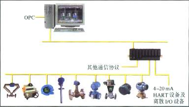
2. WestSakARCO Oilfield, Alaska, USA The oil field is located in the northern region where the United States is rich in oil resources. The natural conditions in this area are very harsh, with extreme temperatures of -50oF~+70oF. In the construction of the oil field, it was subject to great financial restrictions. After visiting the 1996 ISA exhibition, users decided to adopt FF fieldbus technology and chose an integrated fieldbus solution.
The project includes 29 wells. The DeltaV control system uses six H1 fieldbus interface cards, 69 FF3051 pressure transmitters, 38 FFEI-O-MaticELQ800 actuators and built-in AMS management software. The installation began in November 1997 and went into operation on December 26 of the same year. Has achieved very good economic benefits.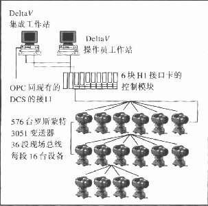 According to statistics, compared with the traditional DCS program, the initial savings of the SF fieldbus used in the WestSak oilfield are as follows:
(1) reduce the connection terminal 84%;
(2) Reduce the number of I/O cards by 93%;
(3) to reduce the control panel space 70%;
(4) Reduce indoor wiring by 98%;
(5) Reduce the maintenance volume by 50~80% due to remote diagnosis;
(6) 90% reduction in configuration time required to expand the field;
(7) Save cable costs by 69%.
In addition to these significant savings, the use of built-in AMS management software in the maintenance management makes it possible for technicians to diagnose the status and faults of field devices in the control room, which greatly reduces unnecessary on-site inspections. The significance of the ARCO field, which is severely cold in winter, is particularly significant.
3. The latest development of the FF fieldbus system in China In August 1998, Fisher-Rosemont signed the first FF fieldbus application contract with the Xi'an National Electric Power Research Institute and Xi'an Jiaotong University. This project is used for high-precision thermal testing of large-scale turbines in thermal power plants. Including DeltaV control system, AMS management software, more than 120 FF pressure and temperature transmitters.
In cooperation with the unit maintenance, the system has conducted thermal tests on the 300MW steam turbine of the Zhangjiakou Power Plant in Hebei from April 23 to May 22, 1999. The DeltaV fieldbus control system did not show any faults and abnormalities during more than 20 days of testing, and it fully demonstrated its superiority in many aspects such as reliability, high precision, flexible and simple installation and configuration, and rapid equipment diagnosis.
On March 31 this year, the fieldbus system integration laboratory established by Fisher-Rosemount and the Department of Automation of Tsinghua University was officially opened. This system is the first set of instruments and systems that have passed FF certification in China. It includes a set of DeltaV control system, AMS equipment management system, FF3051 pressure transmitter, FF3244MV multi-parameter temperature transmitter and FFDVC5000 intelligent valve. The Tsinghua University Fieldbus Integration Lab integrates the Fisher-Rosemount integrated FF system as an important part of it. It integrates with other fieldbus network segments, LANs, and the Internet to send real-time running status and data into the field. Comprehensive data networks provide good conditions for carrying out experimental research on enterprise network information integration and remote control technologies.
So far, Fisher-Rosemont has put several FF control systems into operation in China. At the same time, it has signed dozens of FF control system contracts, including Ningxia Dayuan Refining & Chemical Company, Suzhou Carbon Black Factory, and Tangshan Cement Factory. , Shanxi Xingping Chemical Plant, Guangzhou Petrochemical Refinery, Jilin Chemical Fiber, Yunnan Jiangchuan Phosphate Fertilizer Plant and other users.
VII. Concluding remarks In enterprise information systems, fieldbus is the underlying control network that connects the on-site smart devices. Most of the traditional instrumentation communication uses current and voltage analog signals. The control system uses a closed distributed system. Information exchange between field devices and between the system and the enterprise's integrated information system is very difficult. On the one hand, fieldbus realizes digital communication between factory automation equipments on the one hand, and can complete some control tasks traditionally performed only by the control system. On the other hand, as an open network at the bottom of the site, it communicates the link between the field devices and the upper information system. It not only can complete the measurement and control tasks, but also provide a wealth of equipment management information, thereby improving the level of enterprise automation and management. Compared with the traditional DCS structure, it has obvious technical advantages.
Compared with other field buses, the design and development of FOUNDATION fieldbus are all based on the characteristics of process industries. They are open, interoperable, dispersive of system architecture, unique functional block technology, and communication implementation. Synchronization and adaptability to demanding field environments (such as intrinsically safe, cable installations and bus-powered) all better meet the needs of process automation.
In China, CFAC is a member of the Foundation Fieldbus Group and is responsible for the support and promotion of FF fieldbus technology. In December 1998, the FF fieldbus exhibition and technical exchange were successfully held in Beijing, which attracted a large number of professionals in the automation industry. In March 1993, the FF Foundation Fieldbus End-User Association was established in Beijing. This indicates that the application of FF technology has entered a new stage in China.
In the early 1980s, an intelligent instrument based on the HART protocol was introduced. The HART protocol adopts FSK frequency shift keying technology. Its digital signal is modulated to a 4~20mA analog signal, which realizes digital communication and does not interfere with the transmission of analog signals. Due to its unique Device Description Language (DDL) and other technical features, HART smart meters have been widely accepted and applied.
After the emergence of smart meters, people have great interest in the application of digital communication technology in the field of automatic control. This is because smart meters have increased equipment database, self-diagnosis, fault prediction and other functions compared to traditional meters, making the appearance of the instrument a new look. However, it is an extremely complicated process to form a standard for digital communications that can be targeted at process control, is technically advanced, and can be widely accepted by major instruments and control manufacturers and users. Until June 1994, the two major international organizations ISP (InteroperableSystemProtocol) and North American WorldFIP (WorldFactoryInstrumentationProtocol) organizations formally merged to produce the Fieldbus Foundation.
The Fieldbus Foundation is a non-profit neutral organization composed of more than 100 major control and inspection instrument manufacturers and end users in the world. Its purpose is to develop fieldbuses that are adaptable to process control, openness, interoperability, and standards. It also complies with the IEC (International Electrotechnical Commission) standards under development and the SP50 standard of the ISA (American Institute of Instrumentation and Instrumentation), and is widely represented internationally.
The FF fieldbus is an all-digital, serial, and two-way communication protocol for interconnecting field devices such as transmitters, control valves, and controllers. Fieldbus is a local area network (LAN) existing between process control instruments to achieve decentralized process control within the network.
The most fundamental feature of FF fieldbus is that it is developed specifically for industrial process automation. It has perfect measures to meet demanding use environments, intrinsic safety, hazardous situations, variable processes, and bus power supply. Due to the adoption of standard function blocks and DDL device description technology, it is ensured that the products of different manufacturers have good interoperability and interchangeability. In summary, during the complete life cycle of the automation product from design, installation, operation to maintenance, the FF field bus can bring users various benefits.
Second, FF field bus model and technology overview FF field bus in line with ISO (International Standards Organization) defined OSI (Open Systems Interconnection) model. As shown in Figure 1, it mainly includes three parts: Physical Layer, Communication Stack, and User Layer.
The physical layer corresponds to the first layer of the OSI. It accepts messages from the communication stack and converts them into physical signals transmitted on the fieldbus communication medium, and vice versa.
The communication stack corresponds to the second and seventh layers of the OSI. The seventh layer, application layer (AL), encodes and decodes user-level commands. The second layer, the Data Link Layer (DLL), controls the transmission of information through the first layer. The DDL also manages access to the fieldbus through a defined centralized bus scheduler, the so-called LinkActiveScheduler (LAS). The LAS is used to schedule the transfer of information and the exchange of data between control devices. The FF fieldbus does not use the third, fifth and sixth floor of the OSI. The user application layer is not defined by the OSI model but is defined by the FF itself.
The FF data link capability provides an enhanced method of access to control and services for all modern data models. Including Client/Server, Figure 2 Fieldbus Structure Publisher/Subscriber, and Report Distributor. By extending addressing and bridging of secure data transmission, it supports multiple segments at the same time. In addition, it provides more accurate time allocation and synchronization of multi-segment systems, on-line device monitoring and configuration, and online scheduling modification and creation.
1. Physical layer The physical layer is defined according to the standards approved by IEC and ISA and conforms to the physical layer standards of ISAP50.02-1992, IEC1158-2 (1993) and the FF-81631.25kb/s physical layer behavior specification.
The FF field bus uses Manchester-Biphase-L technology coding.
The FF field bus includes H1 and H2 (see Figure 3). The technical specifications of H1 have been completely determined. H2 uses 100Mb/s high-speed Ethernet technology and is expected to release its technical specifications in 1999.
The H1 communication rate is 31.25kb/s, which is suitable for temperature, flow and level measurement applications. Its equipment is directly powered by the bus and can also operate on the original 4-20mA equipment line. H1 can support intrinsic safety (IS) with bus-powered mode. Therefore, an intrinsic safety barrier should be added between the power supply in the safe area and the intrinsically safe equipment in the hazardous area.
The signal waveform of H1 is shown in Fig. 4. The transmitting device transmits a current signal of +10 mA to a 50 Ω equivalent load at a rate of 31.25 kb/s to generate a peak-to-peak voltage of 1 V modulated on the DC power supply voltage (PP ) Voltage signal. The DC voltage range is 9~32V, but in the intrinsically safe application, the allowable voltage range is determined by the safety barrier rating.
The technical specifications of H2 have not been completely determined yet.
2. Communication stack With reference to Figure 2, the following is a brief overview of the work of each layer of the communication stack.
a. Data Link Layer (DLL)
The DLL is located on the second floor and mainly controls the transmission of messages on the fieldbus. It manages access to the bus through the LAS. The DLL is a subset of the existing IEC/ISA DLL.
The DLL defines three types of equipment, namely, basic equipment that cannot become LAS, master equipment that can become LAS, and bridges that can combine field buses into larger networks.
LAS handles real-time process data separately from back-end MMIs (man-machine interface) and downloads. On the bus, only one active LAS is responsible for managing the bus. It has a list of all the devices on the bus. After the device has been approved by the LAS, it can send a transmission packet to the bus.
Communication over the bus is divided into two categories: Scheduled/Cyclic and Unscheduled/Acyclic communications.
For scheduled communications, the LAS has a transmission schedule that works for all data buffers in all devices that need to be periodically transmitted. When the data transmission time of the device buffer arrives, the LAS sends a forced data (CompelData, CD) to the device. Once the CD is received, the device broadcasts or "publishes" data to all devices on the fieldbus. All devices that are configured to receive data are called Subscribers.
Scheduling communication is often used between fieldbus devices to carry out regular, periodic transmission of control loop data.
Unscheduled communication allows all devices on the field bus to have the opportunity to send non-scheduled messages between dispatch packets. The LAS issues a PassToken (PT) to a device. When the device receives the PT, it allows the use of the fieldbus and sends the message. Unscheduled communication is usually used to transmit information such as alarm events, maintenance/diagnostic information, display information, trends, and configuration.
b. Fieldbus Access Sublayer (FAS)
FAS utilizes the scheduling and non-scheduling features of the DLL to provide services for the message sub-layer (FMS). Its service types include three types:
(1) Client/server type: Used for queuing, non-scheduling, user initialization, one-to-one communication between devices. It is often used for operator-generated requests, such as fixed-value changes, alarm confirmations, and device uploads and downloads.
(2) Report Distribution: Used for queueing, non-scheduling, user initialization, and one-to-many communication. Generally used for fieldbus devices to send alarm notifications to the operator console.
(3) Release/Receive Type: Used for buffering (that is, the latest version of the data is retained in the network), one-to-many communication. It is often used for periodic, user function block inputs and outputs such as process variables (PV) and raw outputs (OUT).
c. Fieldbus message sublayer (FMS)
FMS communication services provide a standard method for user applications. With it, each function block can communicate through this bus. It describes the communication service, the message format and the protocol behavior necessary for the user to establish a message. For different object types, the corresponding FMS communication service is defined.
3. The user application module FF module is divided into the following 3 categories.
a. Resource Block
Describe the characteristics of the device, such as name, manufacturer, serial number, etc. Each device has only one resource block.
b. Function Block
It controls the system behavior and its inputs and outputs can be connected via fieldbus. The execution of each function block is precisely scheduled. There can be more than one function block in one user application. FF defines a standard set of function blocks, such as AI, AO, PID, and so on.
In the field device, by setting up function blocks, the expected functions can be realized. For example, a pressure transmitter can include an AI, and a control valve can include a PID and an AO block. In this way, a complete control loop can be formed by the transmitter and the control valve.
It separates the function blocks from the read sensor and command output to the hardware's local input/output functions. They also contain information such as date and sensor type.
4. System Management
In order for the control system to work properly, the function blocks must be executed at precise time intervals and in the correct order.
System management synchronizes the execution of function blocks on the field bus with the communication of function block parameters; it also handles other important system features such as date and time release for all devices, automatic assignment of device addresses, and parameter names or tag numbers (Tag) search and so on.
5. Device Description
In order to ensure interoperability of FF devices, device description techniques are used in addition to guaranteeing the definition of function block parameters and behaviors. DD is similar to the driver used in the PC to contact the operating printer. As long as there is a device DD, any field bus compatible control system or host can operate the device.
FF provides DD for all standard function blocks and converter blocks. Vendors usually develop “long†DDs based on standard DDs to add vendor-specific features such as calibration and diagnostic procedures to the equipment.
6. System Configuration
It is divided into the following two phases.
a. System Design It is similar to the current Distributed Control System (DCS) design, but there are some differences.
The first is the physical wiring, which changes from a 4-20mA analog point-to-point connection to a digital bus line that connects multiple devices to one cable. Each FF device must have a unique physical device tag and a corresponding network address.
b. After the system configuration system design and instrument selection, according to the control strategy, connect the input and output of the functional block of the device, then the configuration can be realized, as shown in Figure 7. If a device is a link master, a separate control loop can be configured, which allows the loop to run continuously without a configuration device or a central console.
Third, FF fieldbus topological structure and common parts features 1. FF field bus topology FF field bus topology is more flexible, as shown in Figure 8, usually includes point to point type, with branch bus type, daisy chain type ( DaisyChain) and tree type. At the same time, these structures can also be combined to form a hybrid structure. Among them, bus-type and tree-type with branch are used more in the project.
a.Buswith Spur with Branch
In this configuration, the fieldbus device is connected to the bus segment through a cable called a branch line. The length of the branch line is from 1m to 120m, and the branch line less than 1m in length is regarded as a splice. It is suitable for applications where the physical distribution of equipment is relatively decentralized, equipment density is low, and new installations are used. Equipment disassembly on the branch has no effect on other equipment.
b. Tree
Devices on a fieldbus segment are connected to a common junction box, terminal, dashboard, or I/O card in a separate twisted pair. It is suitable for applications where fieldbus is locally concentrated, high density, and upgrades of existing equipment to fieldbus. With this topology, the longest length of the spur must be taken into account.
2. Common Component Characteristics a. Cables Various types of cables are available for fieldbus.
Table 1 lists the cable types specified in the IEC/ISA physical layer standard. The Type A cable is the preferred cable that meets the IEC/ISA physical layer conformance test. Alternative type A cables are Type B cables, which are commonly used in new plant and retrofit projects where multiple fieldbuses operate in the same area. Type C and D cables are generally not recommended.
b. Terminator It is an impedance matching module installed at or near each end of the transmission line. Each field bus segment needs two. Its role is to prevent signal distortion and attenuation.
c. Power According to the FF physical layer profile specification, the power supply will be designed into the following three types:
(1) Type 131. The non-intrinsically safe power supply is designed for the power supply of the explosion-proof grid, and its output voltage depends on the explosion-proof grid power (rating).
(2) Type 132. Non-intrinsically safe power supply, not used for intrinsically safe explosion proof grids. The maximum output voltage is 32VDC.
(3) Type 133. Intrinsically safe power supply, in accordance with recommended intrinsically safe parameters.
In order to ensure the normal operation of the fieldbus, the impedance of the power supply must match the network. Whether it is a built-in or external fieldbus power supply, this network is a resistor/inductor network.
IV. Field test of FF in Monsato, USA In November 1995, FF conducted an on-site Beta test at the Monsato Chocolate Bayou plant. The manufacturers participating in the trial included Fisher-Rosemount, Honeywell, Foxboro, Micro-Motion, Yokogawa, Smar, E+H, etc. The host of the trial was Fisher-Rosemount's PROVOX system. The main contents of the experiment include communication scheduling, alarms and online function blocks.
As shown in Figure 9, it is a boiler coolant recovery system in which the appropriate fieldbus measurement and control equipment is installed.
As shown in Fig. 10, the fieldbus area is divided into two parts, areas 1 and 2. Through the H1 bus, related functional blocks are linked into specific measurement and control loops.
As shown in Figure 11, here, the host only assumes the tasks of configuration and monitoring, and the basic measurement and control functions are performed by on-site equipment.
This field test verifies key technologies and demonstrates the interoperability of different manufacturers' products in the same system. Of course, it is only a test system that was dismantled shortly after the test was completed.
After this, at the ISA exhibition in the United States in October 1996, FF showed fieldbus technology that has been completed and obtained control tactics for recognizing 11 fieldbus applications, more than 70 FF devices and 8 control systems from 37 manufacturers. Operate through 13 fieldbus connections.
V. Fisher-Rosemont Integrated Fieldbus Solution Since the introduction of the FF Fieldbus, PlantWeb plant management network structure has brought a profound change to the process management, it combines intelligent field devices, standards and scale Variable platform technology and integrated modular software provide a more efficient and user-friendly approach to improving process performance. On the basis of lower overall price than traditional DCS-centric solutions, PlantWeb provides more features.
Fisher-Rosemont further introduced the integrated fieldbus solution, PlantWeb-Builder, as shown in Figure 12. It mainly includes:
(1) FF measurement and analysis instruments. Such as 3051 pressure transmitter, 3244MV temperature transmitter, 5300 mass flowmeter 8800A vortex flowmeter, 4081pH meter and so on.
(2) FF valve and actuator with digital controller. Such as DVC5000F valve controller and ELQ series valve actuators.
(3) DeltaV with integrated management capabilities (built-in AMS equipment management software) and scalable control system.
(4) Other required equipment such as power supply, protective equipment and junction box.
(5) Technical support for project implementation.
PlantWebBuilder not only fulfilled the technical promise of FF fieldbus, but also added some new features, mainly reflected in:
a. Realize the control in any place Adopt FF technology, the on-the-spot equipment can carry out the control algorithm without relying on the control system, make PID control can be loaded into the on-the-spot equipment.
PlantWebBuilder's unique, anywhere control provides more functionality because in this solution, the common functional blocks used in field devices are exactly the same as in the DeltaV control system. Device-based control has the advantages of improved control response, reduced dead time, and the like; it also reduces the load on the control system so that the control system can perform advanced functions such as batch processing and inspection control.
b. Built-in AMS equipment management software In this program, it is worth AMS management software to enable users to easily check the wiring and configuration equipment in front of a PC or workstation. In practical applications, the user can save the installation cost. More than 30%. At the same time, it is possible to use the diagnostic function of AMS software to check the equipment and issue an alarm signal before the problem is serious, or confirm the fault in the control room before the technician goes on-site inspection, thereby reducing the equipment downtime; and making the site changeable. The working conditions of the feeder and the valve are always kept optimal, improving the consistency and availability of the process.
c. Less Risk and More Flexibility with Integrated Solutions Considering the difficulties users may encounter when initially applying FF fieldbus technology, the integrated solution allows users to use FF fieldbus technology faster. The program's German fieldbus products have been tested not only in the laboratory but also in the field.
It should be emphasized that although PlantWebBuilder's FF integration solution is complete, it is also open, that is, all products that have obtained the FF interoperability test tag, as well as application software that conforms to the OPC standard can be integrated into the solution. And, through the OPC, Modbus, 4 ~ 20mA, HART and discrete I / O can also integrate the user's existing equipment and systems.
VI. APPLICATION EXAMPLES 1. World's first FF fieldbus system for commercial operation On April 15, 1997, at the large-scale chemical plant in Fort Saskatchewan, Canada, the first FF fieldbus system was put into commercial operation. The system includes 96 FF3051 pressure transmitters divided into 6 fieldbus zones, a DeltaV control system, and communicates with the plant's existing DCS system via OPC technology. According to user records, the entire project saves about 30% of investment compared to traditional installations. The 4-digit instrument engineer completed the installation and driving of all transmitters in just 5 hours. Field-installed controllers and I/O cards are used for installation. After the system was successfully put into operation, the user increased the number of transmitters to 576 in the second phase, and part of the control was downloaded to the field instrument, as shown in Figure 13.
2. WestSakARCO Oilfield, Alaska, USA The oil field is located in the northern region where the United States is rich in oil resources. The natural conditions in this area are very harsh, with extreme temperatures of -50oF~+70oF. In the construction of the oil field, it was subject to great financial restrictions. After visiting the 1996 ISA exhibition, users decided to adopt FF fieldbus technology and chose an integrated fieldbus solution.
The project includes 29 wells. The DeltaV control system uses six H1 fieldbus interface cards, 69 FF3051 pressure transmitters, 38 FFEI-O-MaticELQ800 actuators and built-in AMS management software. The installation began in November 1997 and went into operation on December 26 of the same year. Has achieved very good economic benefits.
(1) reduce the connection terminal 84%;
(2) Reduce the number of I/O cards by 93%;
(3) to reduce the control panel space 70%;
(4) Reduce indoor wiring by 98%;
(5) Reduce the maintenance volume by 50~80% due to remote diagnosis;
(6) 90% reduction in configuration time required to expand the field;
(7) Save cable costs by 69%.
In addition to these significant savings, the use of built-in AMS management software in the maintenance management makes it possible for technicians to diagnose the status and faults of field devices in the control room, which greatly reduces unnecessary on-site inspections. The significance of the ARCO field, which is severely cold in winter, is particularly significant.
3. The latest development of the FF fieldbus system in China In August 1998, Fisher-Rosemont signed the first FF fieldbus application contract with the Xi'an National Electric Power Research Institute and Xi'an Jiaotong University. This project is used for high-precision thermal testing of large-scale turbines in thermal power plants. Including DeltaV control system, AMS management software, more than 120 FF pressure and temperature transmitters.
In cooperation with the unit maintenance, the system has conducted thermal tests on the 300MW steam turbine of the Zhangjiakou Power Plant in Hebei from April 23 to May 22, 1999. The DeltaV fieldbus control system did not show any faults and abnormalities during more than 20 days of testing, and it fully demonstrated its superiority in many aspects such as reliability, high precision, flexible and simple installation and configuration, and rapid equipment diagnosis.
On March 31 this year, the fieldbus system integration laboratory established by Fisher-Rosemount and the Department of Automation of Tsinghua University was officially opened. This system is the first set of instruments and systems that have passed FF certification in China. It includes a set of DeltaV control system, AMS equipment management system, FF3051 pressure transmitter, FF3244MV multi-parameter temperature transmitter and FFDVC5000 intelligent valve. The Tsinghua University Fieldbus Integration Lab integrates the Fisher-Rosemount integrated FF system as an important part of it. It integrates with other fieldbus network segments, LANs, and the Internet to send real-time running status and data into the field. Comprehensive data networks provide good conditions for carrying out experimental research on enterprise network information integration and remote control technologies.
So far, Fisher-Rosemont has put several FF control systems into operation in China. At the same time, it has signed dozens of FF control system contracts, including Ningxia Dayuan Refining & Chemical Company, Suzhou Carbon Black Factory, and Tangshan Cement Factory. , Shanxi Xingping Chemical Plant, Guangzhou Petrochemical Refinery, Jilin Chemical Fiber, Yunnan Jiangchuan Phosphate Fertilizer Plant and other users.
VII. Concluding remarks In enterprise information systems, fieldbus is the underlying control network that connects the on-site smart devices. Most of the traditional instrumentation communication uses current and voltage analog signals. The control system uses a closed distributed system. Information exchange between field devices and between the system and the enterprise's integrated information system is very difficult. On the one hand, fieldbus realizes digital communication between factory automation equipments on the one hand, and can complete some control tasks traditionally performed only by the control system. On the other hand, as an open network at the bottom of the site, it communicates the link between the field devices and the upper information system. It not only can complete the measurement and control tasks, but also provide a wealth of equipment management information, thereby improving the level of enterprise automation and management. Compared with the traditional DCS structure, it has obvious technical advantages.
Compared with other field buses, the design and development of FOUNDATION fieldbus are all based on the characteristics of process industries. They are open, interoperable, dispersive of system architecture, unique functional block technology, and communication implementation. Synchronization and adaptability to demanding field environments (such as intrinsically safe, cable installations and bus-powered) all better meet the needs of process automation.
In China, CFAC is a member of the Foundation Fieldbus Group and is responsible for the support and promotion of FF fieldbus technology. In December 1998, the FF fieldbus exhibition and technical exchange were successfully held in Beijing, which attracted a large number of professionals in the automation industry. In March 1993, the FF Foundation Fieldbus End-User Association was established in Beijing. This indicates that the application of FF technology has entered a new stage in China.
Welding Flux,Sumberged Arc Welding Flux,Fused Flux
Popular Mesh Belt Co., Ltd. , http://www.nspolyesterfabric.com